|
Physics 1b Practical – QP Problems – 2012
QP 1
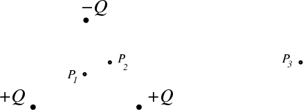
Consider three point charges of magnitudes +Q, +Q, and -Q, located at the verticies of an equilateral triangle of sides a. (Let the +Q’s be at the ends of the base and the -Q at the apex.)
|
|
a) Draw this configuration at the center of your paper with a ≈ 1 inch. Mark with a small × the location or locations of any points where the magnitude of the electric field is zero in the plane of your paper.
b) If the origin of coordinates, r=0, is located at the center of the triangle, what is the limiting form of the total electric field E(r) valid for r ≫ a?
c) Sketch the field lines in the plane of the triangle. Let your diagram continue out to the edge of your paper, and place an arrow on each line indicating its orientation.
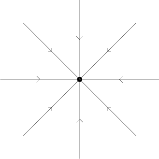
In reality, there are infinitely many lines. So we shall agree on the following convention for this problem: in a given plane, let there be eight lines coming out of each point charge of magnitude +Q. So, for example, an isolated -Q would look like
|
(You might practice on a rough sketch, keeping in mind the various properties that these lines possess, e.g., near the charges, far from the charges, symmetries of the problem, your answers to parts a) and b), etc. When you are as confidant as you can be, make your final version — and make it clear to the grader which one that is.)
d) Locate points P1, P2, and P3 on your figure and draw a vector representing the value of E at each of those three points, with each vector beginning (i.e., with its tail) at the respective point. The overall scale of the three is up to you, but their relative magnitudes should reflect the magnitudes of the E field.
QP 2
|
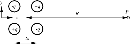
An electric quadrupole is a particular configuration of charges which sum to zero but whose effects at a distance do not quite cancel. One example of electric quadrupole is formed by four charges located at the vertices of a square of side 2a. Point P lies a distance R from the center of the quadrupole on a line parallel to two sides of the square as shown.
(a) What is the direction of the electric field at point P?
(b) Write down an exact expression for the quadrupole electric field E at point P.
(c) Show that for R ≫ a the electric field reduces to the form E ≈ α∕R4 and give an expression for α in terms of the parameters specified.
QP 3
(a) Two point charges, each of charge +Q, are separated by a distance d. What is the set of points in space at which the total electric field due to these two charges is zero?
(b) Two point charges, one of charge +Q and the other of charge -Q, are separated by a distance d. What is the set of points in space at which the total electric field due to these two charges is zero?
QP 4
|
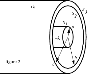
Figure 2 shows a section through two long concentric cylinders having equal and opposite charge per unit length, λ.
(a) If the two cylinders are insulators with charge uniformly distributed throughout, what is the magnitude and direction of the electric field in all space, i.e., r < a, a < r < b, b < r < c, r > c?
(b) If the two cylinders are conductors, what is the magnitude and direction of the electric field in all space?
(c) If the two cylinders are conductors, how much charge per unit length is on each surface, labeled S1, S2, and S3 in figure 2?
QP 5
|
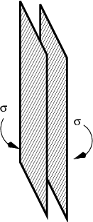
Two large nonconducting sheets of positive charge, carrying the same surface charge density σ, face each other. Considering only points not near the edges and whose distance from the sheets is small compared to the dimensions of the sheets, what is the electric field E at points
(a) to the left of the sheets?
(b) between the sheets? and
(c) to the right of the sheets?
QP 6
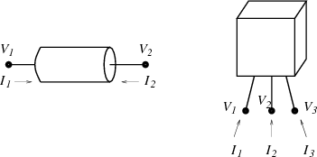
Many simple devices have two electrical contacts or leads. Common examples are resistors, bulbs, diodes, thermistors, batteries, and capacitors. We can label the voltages and incoming currents as V 1, V 2, I1, and I2, as shown in the figure below.
|
Nevertheless, we generally speak of an I and V to describe such a device.
What are I and V in terms of V 1, V 2, I1, and I2?
What is the key assumption regarding the total charge Q of the device?
There certainly are other devices with more electrical leads. For example, a transistor has three, and voltages and currents can be defined as in the figure above.
Assuming that the total charge on such a three lead device is always zero, how many relevant variables are there, and what are they (in terms of the ones defined in the figure)?
We often imagine that the physics of the device determines some relation between the current and voltage parameters, e.g., the I - V curve of a two lead device. However, the situation can be more complicated.
QP 7
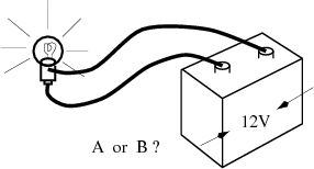
Two car bulbs, bulb A and bulb B, look superficially similar. However, when bulb B is connected to a 12 V car battery, its filament glows much brighter than did bulb A’s when A was connected to the battery.
|
(a) Which bulb draws more current from the battery, A or B?
(b) Which bulb has a higher resistance?
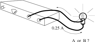
A current-controlled power supply is set so that it delivers precisely 0.25 amps over a very wide range of load resistances.
|
(c) When attached to this current-controlled power supply set at 0.25 amps, which glows brighter, bulb A or bulb B?
EP 1
A Physics 8 student attempts to measure the current I that flows through an incandescent flashlight bulb as a function of the voltage, V , applied across the bulb. The circuit she uses looks like the following
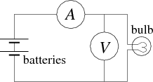
|
where the circled V and A are the volt meter and ammeter. The voltages are applied by connecting successive numbers of AA batteries, and the meter readings are as follows:
I(V = 1.62V) = 0.070A; I(V = 3.18V) = 0.106A; I(V = 4.65V) = 0.136A; I(V = 6.25V) = 0.160A.
Add to this data set the obvious assumption for the current I at V = 0.
Assume for now that the meters are ideal. An ideal voltmeter presents infinite resistance so that no current flows through it. An ideal ammeter presents zero resistance so that there is no voltage drop across it when current flows.
Using this data, sketch a plausible curve for I as a function of V for the range provided.
For an Ohmic resistor, the curve of I versus V is a straight line, and at any point I∕V and dI∕dV are equal. More generally, that is not true. In such a case, which represents the actual resistance at that voltage and current? (The other is, nevertheless, of considerable practical significance.) Explain in words what it means.
Estimate the relative change in resistance of the bulb filament between room temperature (around 0 V) and 6 V. Assume the filament is tungsten and estimate the temperature in degrees C of the filament at 6 V. Does your answer make sense relative to other “red hot” temperatures (e.g., the surface of the sun, fires, glowing hot)?
QP8
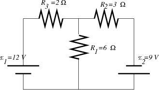
|
Consider the circuit shown with resistors R1, R2, and R3 and battery voltages  1 and 2 as
indicated.
1 and 2 as
indicated.
(a) What currents i1, i2, and i3 flow through R1, R2, and R3 respectively?
(b) What power is dissipated in each of the resistors?
(c) Compare the power supplied by the batteries to the power dissipated in the resistors. Is total energy conserved?
QP 9
A circuit consisting of a voltage source of magnitude V o, three resistors with resistances R1, R2, and R3, and a switch, S, is constructed as shown. We are interested in the voltages, V 1 and V 2, which are defined by the potential differences between the points A, B, and C indicated in the figure.
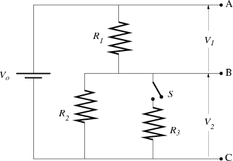
|
There are a couple of common conventions regarding circuit diagrams that might deserve mention. Wires that just end, e.g., at A, , and C above, are just that – unless specified otherwise. In particular, nothing further is connected there, except, perhaps, a voltmeter, which, if ideal, does not disturb the circuit. If those wires were to be connected to something else, current might flow there, and that might change the currents and voltages in the part of the circuit in the original figure.
In the figure above, if, indeed, there is current flowing in or out of A and C, the values of those currents would have no impact on the voltages at A and C or anywhere else in the figure. (Pause, if this is not yet obvious.) In contrast, the voltage at B would vary with the value of the current flowing out at B.
(a) What is V 1 + V 2 with switch S open?
(b) What is V 1 ÷ V 2 with switch S open?
(c) What is V 2 in terms of V o and the values of the resistances?
The circuit with the switch open, i.e., with only R1 and R2, is of considerable practical value; it is known as a voltage divider. A fixed voltage V AC is divided into two parts, whose values depend on the resistors chosen in a very simple way. Often a variable resistor is used to allow V BC to be adjusted at will.
QP 10
(Refer to the figure in the previous problem.) The simple result for the voltage divider (open switch S) is valid if no current flows out of B, the middle lead. Attaching a voltage divider to a load is modeled by the circuit with switch S closed and with R3 representing the load on the R1 -R2 voltage divider. The voltage across R3 is not the same as the open-switch V 2.
(a) What is V 1 + V 2 with switch S closed?
(b) What is V 1 ÷ V 2 with switch S closed?
(c) What is V 2 in terms of V o and the values of the resistances?
QP 11
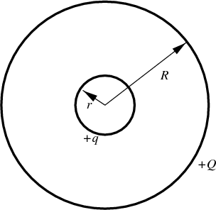
|
Two isolated, concentric, spherical, conducting shells of radius r and R carry positive total net charges q and Q, respectively. The shells are very thin compared to the radii.
(a) What is the potential at the surface of the large sphere, assuming V = 0 at infinity?
(b) What is the potential of the small sphere?
(c) Calculate the potential difference between the spheres, and indicate which one is at a higher potential.
(d) Now the spheres are connected with a fine conducting wire so that charge could redistribute between them. Will the charge move, and, if so, which direction will it flow? What will be the final charge on each sphere?
QP 12
For a warm-up, make a small sketch (2”x2” would do) of the I - V curve of each of the following: an ideal conductor (R = 0), an ideal insulator (R = ∞), and an ideal battery.
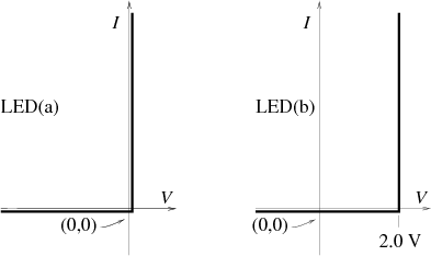
A diode is a two-lead device whose principle role is to allow current to flow in one direction and not the other. As such, the crudest version of its I -V curve is given by the figure labeled LED(a) below. In particular, for any voltage that is applied in the “backward” or by definition negative direction, no current flows. In the “forward” or positive direction, any current can flow, and the voltage difference across the diode is zero.
A somewhat more realistic description includes a threshold voltage. For any applied voltage less than the threshold, no current flows. And, any current flowing in the positive direction is accompanied by a voltage drop equal to the threshold voltage. This is illustrated in the figure labeled LED(b) below.
Different diode materials produce different characteristic thresholds. In some applications, the threshold value is the diode’s most relevant characteristic. In other applications, the particular threshold value is so much smaller than all other relevant values that it can safely be ignored.
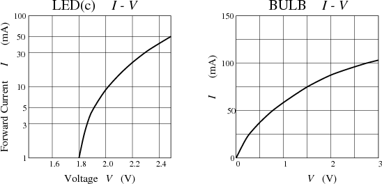
The actual I -V curve of a real diode rises roughly exponentially in the forward direction (until the diode fails). It is very small in the backward direction. “Failure” there, at some substantial negative voltage is often accompanied by a narrow voltage interval in which the diode conducts very well, before ultimately blowing up at sufficiently negative voltage.
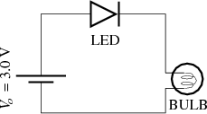
An LED (Light Emitting Diode) and a small light bulb are connected in series to a 3.0 V battery. (The battery internal resistance is negligible, and the bulb I-V curve is reproduced below.)
|
(a) What would be the current, I, in the circuit if the I-V curve of the LED were given by the simplest possible idealization of diode performance, indicated in the graph below labeled LED(a)?
|
(b) What would be the current, I, in the circuit if the I-V curve of the LED were given by the slightly more sophisticated idealization of diode performance, indicated in the graph labeled LED(b)?
|
(c) Estimate the actual current, I, in the circuit using the measured I-V curve of the LED, represented in the graph above labeled LED(c).
QP 13
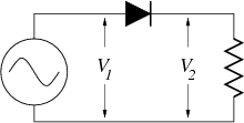
A power supply produces a voltage that varies sinusoidally with time between ±5 V at 60 Hz. It is connected to a diode and a resistor, as shown.
|
Voltages V 1 and V 2 are shown below, as the dashed and solid curves, respectively:
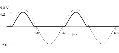
|
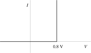
The voltage drop across the diode corresponds to a diode I - V curve something like the following:
|
Four such diodes can be assembled into a diode bridge:
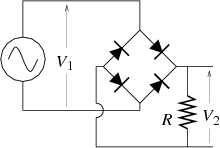
|
Assuming the power supply V 1(t) is as sketched above and the diodes can be characterized by the I - V curve given above, sketch V 2(t) for two cycles of the power supply oscillation. Label all salient values.
You probably won’t be able to write down quations and solve them to figure out what happens here. Instead, imagine a particular time at which V 1 is positive. Current will flow. Where? As it flows, the voltage along the way typically drops (or stays the same where the resistance is zero — or increases where there is a source of voltage. Then try a similar analysis at a time when V 1 is less than zero.
QP 14
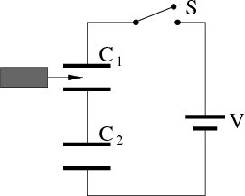
|
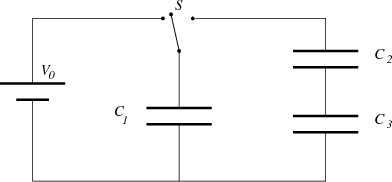
When the switch S is thrown to the left, the plates of the capacitor C1 acquire a potential difference V 0. C2 and C3 are initially uncharged.
(a) What is the initial charge Q1 on capacitor C1?
(b) The switch is now thrown to the right. What are the final charges q1, q2, and q3 on the corresponding capacitors? Express your answers in terms of V 0, C1, C2, and C3.
QP 15
Two capacitors, both initially completely uncharged, of capacitance C1 and C2 are connected to an ideal, constant voltage source of magnitude V o, as shown in figure A below. The voltages across the capacitors are V 1 and V 2, respectively.
(Express your answers to the following two questions in terms of V o, C1, C2, and Rload.)
a) What is V 1∕V 2 for the circuit in figure A? (Hint: The capacitors were initially uncharged. What is the relation between their charges, Q1 and Q2, after V o is applied?)
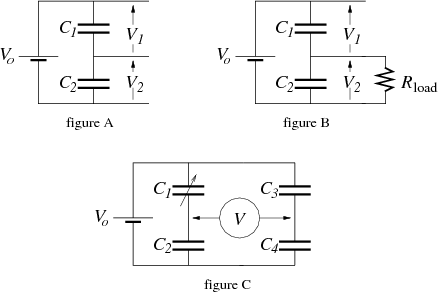
|
This configuration is not very useful as a power supply, as can be seen by considering figure B, where a load resistance, Rload is placed across V 2. Immediately upon making the connection, there will be some time-dependent currents. However, after a substantial time has elapsed, the circuit will settle into a steady state.
b) What is V 2 in this steady state?
Now consider the ideal voltage source V o connected to four capacitors, as shown in figure C above.
An ideal voltmeter is attached as indicated by the circled V , and the variable capacitor C1 is adjusted so that the voltage read by that meter is zero.
c) What is C4 in terms of C2, C3, and the adjusted value C1?
QP 16
|
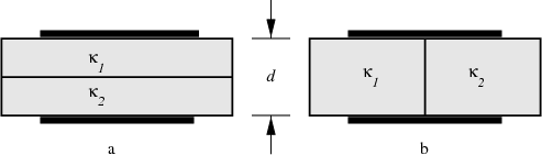
A parallel plate capacitor with plates of area A is filled with two dielectrics (of dielectric constants κ1 and κ2. Each dielectric slab has thickness d/2.
(a) Can this arrangement be equivalently viewed a two capacitors in series or parallel? If so, which?
(b) Find the capacitance of the arrangement in figure 7a.
(c) Now consider the arrangement in figure 7b, where each dielectric occupies half the volume. Can this arrangement equivalently be viewed as two capacitors in series or parallel? If so, which?
(d) Find the capacitance of the arrangement in figure 7b.
QP 17
Rufus and Dufus, two barefoot lads, are fascinated by a Van de Graaff generator. Its upper metal sphere has a radius of 20cm. On this particular day, they note that the generator is capable of producing sparks to a similar size grounded sphere that are as much as 15cm in length. (That number depends on the humidity and the cleanliness and precise mechanical adjustment of the machine.) They both want to “feel” the charge, like electricians of old (i.e., the 18thCentury).
Rufus takes his 1000μF capacitor (“big blue”) from his ZAP! kit, attaches long wire leads to each end, connects one lead (the proper one) to ground and approaches the maximally charged Van de Graaff sphere with the other. There’s a spark between the sphere and the capacitor lead, and then he makes proper metallic contact between that lead and the sphere.
Dufus points out the all of the original charge is still there, now just distributed somehow between the sphere and the attached side of the capacitor.
(a) Estimate the fraction of the original Van de Graaff charge that still resides on the sphere.
“OK,” says Rufus, “Right you are,” and he touches the sphere with his finger.
For the present purposes, model the electrical properties of each boy from finger tip to feet as a 20kΩ resistor to ground.
(b) What is the maximum current that flows through Rufus’ body?
That current has a characteristic exponential decay for its time dependence.
(c) What is the 1/e time for that current?
Dufus, observing there wasn’t all that much zap to Rufus’ experience, charges up the Van de Graaff again to its maximum and tries something else. He foregos the 1000μF capacitor and simply approaches the metal sphere with his bare finger. Again, there is a spark, this time from sphere to finger. For the present purposes you should assume that once the spark forms, the intervening air is a conductor with negligible resistance compared to that of Dufus’ body. In other words, he establishes a conductive path from sphere to ground with a resistance of 20kΩ (essentially all of which is skin).
(d) What is the maximum current that flows through Dufus’ body?
(e) What is the characteristic exponential decay 1/e time for that current?
QP 18
The Leiden jar, named after the city of its origin and developed in the mid-18th Century, was the first really effective design for storing charge, i.e., a capacitor. It consisted of a wide-mouth glass jar, lined with lead foil and wrapped on the outside with another piece of lead foil. The two pieces of foil served as the metallic capacitor “plates.” Contact with the outer foil was direct, while contact with the inner foil was achieved via a metal chain that hung from the center of an insulating wooden stopper down to the (inner) bottom of the jar (not shown in the accompanying sketches).
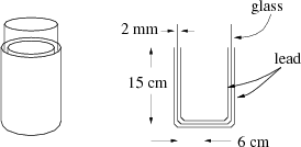
|
In the following, please use these dimensions: The glass is 2mm thick. The foil covered area is cylindrical in shape, of height 15cm and radius 6cm. Note also that the bottom of the jar is foiled inside and out.
(a) Estimate the capacitance of the Leiden jar as described.
(b) What is the maximum charge that can be stored — before there is electrical breakdown, i.e., sparking between the plates?
To see how much of an improvement this is over storing charge on an isolated conductor, consider an isolated, hollow, metal sphere, such as the sphere on a Van de Graaff generator.
(c) Estimate the capacitance of an isolated, hollow, metal sphere of radius 10cm.
(d) What is the maximum charge that can be stored on the sphere — before there is corona discharge to the air?
QP 19
|
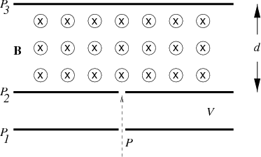
In the mass spectrometer shown, protons (mass mp and charge e) are injected at point P and accelerated by the voltage V across a pair of pair of parallel plates, P1 and P2. The protons then enter a region of uniform magnetic field B, directed into the page. The top of the spectrometer is defined by a third plate P3, spaced a distance d above the second plate.
(a) Will the protons be deflected to the right or the left as they enter the magnetic field?
(b) What is the velocity of the protons as they enter the magnetic field, expressed in terms of the constants given? (Their pre-accelerated velocity is negligible.)
(c) What maximum voltage, V, can be applied between the plates and have the protons not strike the top of the spectrometer?
(d) If the particles were deuterons (twice as massive as protons but with the same charge, does the voltage found in part (c) increase, decrease, or stay the same?
QP 20
Over the past 25 years, a great many surprising discoveries and major advances in the understanding of electrons in solids have come from the study of a fabricated system in which electrons are confined to move in a 2-dimensional plane at the interface of two (insulating) crystals. Making the systems small, very clean, and very cold allows individual electrons to move in that plane essentially as if they were free particles, oblivious to the atoms of the solid. Typically a strong magnetic field is applied perpendicular to the plane of motion. (The interesting complications — that we will ignore for this problem — arise from quantum mechanics and the presence of many other electrons in the plane that exert Coulomb forces on each other.)
When an electron hits the edge of its planar area of motion, it bounces elastically off the edge, with angle of incidence equaling angle of reflection, just like an ideal ball bouncing off a wall.
In the spirit of these experiments, consider a single particle of mass m and charge -Q (i.e., with -Q < 0) moving on a square, 2-dimensional surface of dimensions L × L. If the particle encounters the boundary, it rebounds elastically, with equal angles of incidence and reflection. A magnetic field of magnitude B is applied, pointing perpendicular to the plane — and out of the page as drawn in the figure. The particle is initially located at the point labeled P, which is d from one edge and L∕2 from the other. It has an initial velocity v which is parallel to the nearby side as indicated.
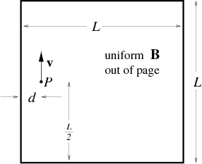
|
The parameters in the problem satisfy the following relations:
L = 8d
v = 
Draw the L × L square on your paper, mark the initial point P, and then sketch the complete orbit of the particle. Include an occasional arrowhead on the orbit to indicate the direction of motion along the line.
QP 21
|
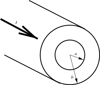
A hollow cylindrical conductor of inner radius a and outer radius b (cross section shown above) carries a total current I uniformly distributed over its cross section.
(a) Find an expression for the magnitude of the magnetic field B for points inside the body of the conductor, i.e., a < r < b.
(b) What is the direction of the magnetic field?
(c) Make a rough plot of the general behavior of B(r) from r = 0 to infinity.
QP 22
An insulating rod of length L and diameter d (with d ≪ L) has a uniform, positive charge density and total charge Q (with Q > 0). As suggested by the accompanying sketch, the length of the rod is parallel to the x-axis (across the page) and the rod has a velocity v which points along the positive y-axis (up the page). This all takes place within a uniform magnetic field B, which points along the positive z-axis (out of the page).
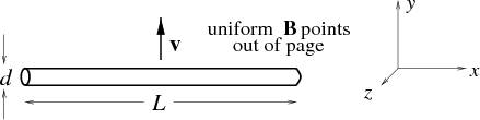
|
(a) What is the total magnetic force FB (magnitude and direction) on the rod?
As the rod moves, it sweeps out an area in the x-y plane. For example, in a time interval ΔT, it sweeps out an area L×v × ΔT. We say that the (time) rate of sweeping area is L×v, i.e., the area swept per unit time. There is a magnetic flux ΦB associated with such an area.
(b) What is the rate of flux,  , swept by the rod?
Consider now a neutral rod made out of a metallic conductor, with the same dimensions and velocity in the same magnetic field as described above. Since it is neutral, the total magnetic force on the rod is zero. However, the magnetic field certainly has some effect. In particular, it pushes plus charges one way and negative charges the other. Since the charges are constrained to remain within the rod, their distribution reaches an equilibrium configuration such that the net force on each charge, i.e., the sum of the magnetic force and the electric forces due to all the other charges, is zero.
(c) What is the electric field E (magnitude and direction) at the geometric center of the rod due to the magnetically induced charge distribution?
(d) What is the electric potential difference between the two ends of the rod?
QP23
A charged particle with initial speed v, charge q, and mass mtraces the path shown below as it moves through a square region of uniform B field and a parallel plate capacitor. For the questions below, ignore edge effects for the magnet and capacitor.
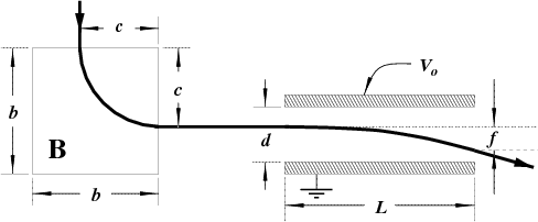
|
QP24
|
Two capacitors are connected in series with a battery through a switch. A dielectric slab is inserted between the plates of one of the capacitors, as shown.
QP25
Intermittent windshield wipers use a circuit that looks roughly as follows:
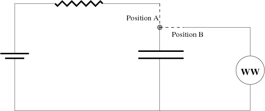
|
The switch is initially in Position A. If the current in the circuit falls below 10-6 amps, it switches to Position B. The circuit element “WW” schematically represents the windshield wiper mechanism: when current flows through it, the wipers sweep once. It has a very small resistance, so the capacitor rapidly discharges into WW. After the capacitor discharges, the switch returns to Position A.
The voltage output of the battery is V o = 3 volts, the resistor has resistance R = 106 ohms, and the capacitor has capacitance C = 2 microfarads. Suppose that the capacitor consists of air filled, parallel plates with separation 10-4 m.
The designers of this car rather stupidly placed this circuit so that oil with dielectric constant κ = 10 can leak into the capacitor.
Because cars are typically rather dirty, the oil that fills the capacitor is not likely to be pure. Suppose that the impure, dirty oil has a dielectric strength of 104 Volts/meter.